
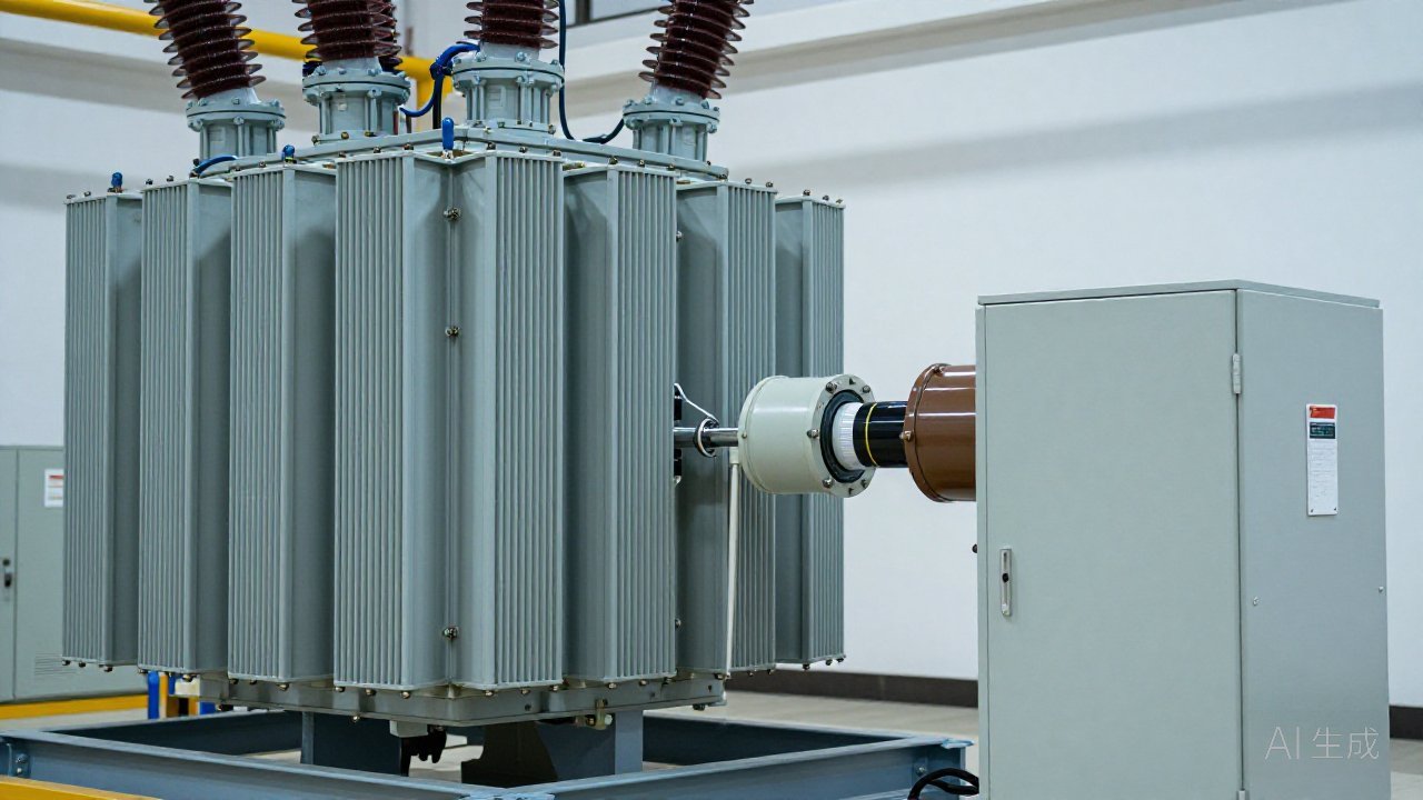
The on-load tap changer is the only component inside a power transformer that is expected to draw an arc in normal operation. It does so inside its own oil compartment, thousands of times a year, while the main tank stays quiet. That reorganises the problem of OLTC partial discharge monitoring: the difficulty is not hearing a discharge, it is separating one from the switching arcs that are supposed to be there.
Why the tap changer needs its own PD channel
Main-tank partial discharge monitoring usually relies on a bushing tap, a UHF sensor through an oil valve, or an acoustic sensor on the tank wall. None of those paths lead into the diverter switch compartment, which is separated from the main tank by an insulating barrier and often by its own oil volume. A defect on the tap-changer insulation boards, on the transition resistors or on the contacts can develop for months without appearing on any main-tank channel. By the time it reaches main-tank oil, it has crossed the barrier — the condition the monitoring was meant to catch early.
The tap changer also carries the highest density of mechanical wear in the transformer. Contact erosion, carbonised oil, loose fasteners and degraded resistor elements can all initiate discharge, and a unit that taps frequently — a converter transformer, an arc furnace transformer, or one controlling a volatile load — puts the OLTC at the front of the risk list on duty cycle alone.
What makes OLTC PD harder to read
A diverter switch produces a burst of broadband energy at every operation. Acoustic sensors hear the mechanical clunk; UHF sensors see a transient; an HFCT on the earth strap sees a current pulse. In a conventional OLTC partial discharge monitoring setup these events look like discharge, and they arrive at rates set by the grid rather than by the insulation. Without an event signal from the tap-changer control, the system cannot tell a normal transition from a developing defect, and any threshold low enough to catch the defect will alarm on every tap change.
The practical answer is event gating: time-stamp each tap-change operation, treat the following window as expected activity, and evaluate the intervals between operations as the diagnostic region. This is the same interference-rejection logic described in PRPD and PRPS pattern analysis, except that here the interference source is known, repeatable and scheduled.
Four sensing paths, four blind spots
| Path | What it sees | Blind spot |
|---|---|---|
| Acoustic (AE) on the OLTC tank wall | Discharge and mechanical events in the compartment; good source location on a large tank | Attenuation through barriers; mechanical noise from the diverter switch |
| UHF through an OLTC inspection hatch or valve | Fast discharge pulses; immune to acoustic noise | Requires an access point; sensitivity depends on internal geometry |
| HFCT on the OLTC earth strap | Pulse current from discharge to earth | Mixed with switching current; needs careful gating and shielding |
| OLTC oil DGA | Gas generated inside the compartment over time | Slow; no location; cannot see a defect that is not yet gassing |
These paths are complementary, and the comparison of UHF, AE, HFCT and RF is set out in partial discharge detection methods. For an OLTC, the useful configuration is usually one electrical path plus one acoustic path, because the two fail differently under mechanical noise.
Separating switching arcs from discharge
Three features carry the decision. First, timing relative to the operation: expected switching activity follows the tap-change command within milliseconds, while a discharge persists into the quiet period afterwards. Second, repetition: switching occurs when the controller commands it, while discharge tends to repeat at power-frequency phase positions and to grow. Third, trend across operations: a defect shows a rising fingerprint over hundreds of operations, even when each event looks unremarkable.
Gas data from the OLTC compartment must be interpreted on its own terms rather than merged with main-tank results, because the oil volumes and gas sources are separate — see OLTC dissolved gas analysis.
Can OLTC partial discharge monitoring replace OLTC DGA?
No. They answer different questions: DGA reports what the oil has accumulated, PD monitoring reports what is happening now. A slow thermal problem may produce gas with little discharge, and a developing discharge can be visible electrically long before the compartment oil is sampled. Running both on the same time base lets an operator tell whether rising gas came from discharge or contact heating.
What should an OLTC PD RFQ specify?
Ask for the sensing path, the event interface to the tap-changer controller, the gating logic and the quiet-period evaluation window, the frequency band of each channel, and how tap-change events are recorded alongside PD data. The permanent PD monitoring specification guide covers the rest of the checklist.
The TPD-400 partial discharge monitoring system is designed for continuous transformer PD monitoring and is designed in line with IEC TS 62478:2016, GB/T 42287, IEC 61850 (DL/T 860) and DL/T 1498.1, with sensing points configured for the compartments being monitored. Where PD is only one of several signals you need, PD versus DGA monitoring explains how the two fit together, and the DGM-900 platform covers the dissolved-gas side of the same transformer. To scope an OLTC configuration, contact the PAS DGA engineering team.