
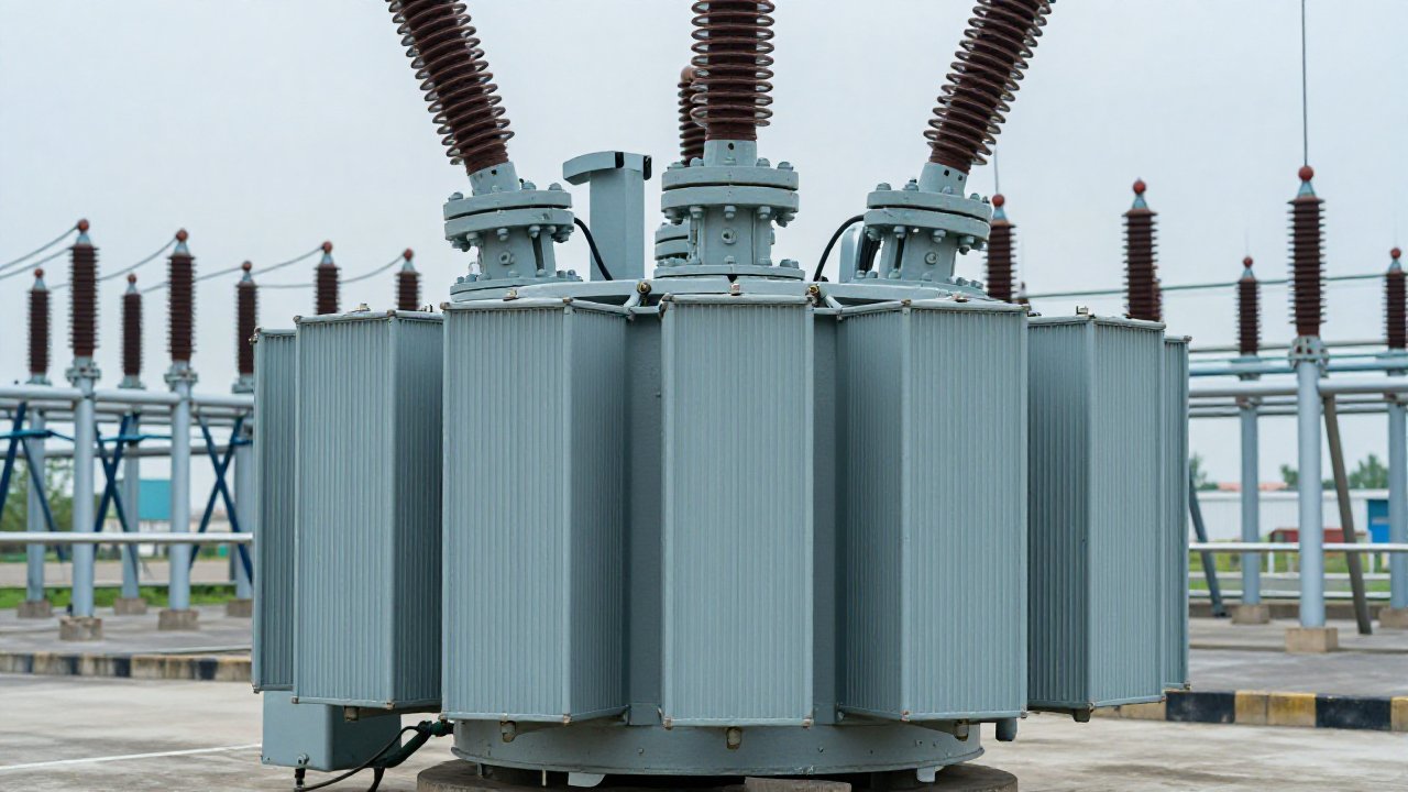
June 2026 brought a paper from TriboTech ApS titled “DGA in Load Tap Changers—Why LTC Oil Isn’t the Main Tank”, and a 2026 study in the International Journal of Science applied the IEEE C57.139 outlier method to vacuum, resistance and separate-compartment tap changers. Both land in one place: OLTC dissolved gas analysis is a discipline of its own.
An on-load tap changer (OLTC) is the only component of a transformer designed to make and break current. Its diverter switch arcs in oil thousands of times over a service life, and that oil does not behave like the oil in the main tank. IEEE C57.104-2019 excludes LTC-coupled compartments from its scope and defers them to IEEE C57.139.
Why the tap-changer compartment is not the main tank
A diverter switch compartment holds tens to a few hundred litres of oil against tens of thousands in the main tank, so the same mass of gas gives a far higher concentration. It has no cellulose, so carbon oxides lose the paper-degradation meaning they carry in the main tank—and it is designed to arc.
The boundary between the two is not gas-tight. Seals and the dividing wall can pass decomposition products, so a tap-changer fault sometimes surfaces first as a rise in the main tank—a migration path IEEE C57.139-2015 treats as part of the evaluation.
What healthy tap-changer oil looks like
Hydrogen and acetylene are routine products of diverter-switch arcing in a healthy OLTC. That breaks the main-tank rule that acetylene means arcing, and it is why this compartment needs its own interpretation scheme.
The designs do not all behave alike
A separate-compartment OLTC keeps diverter oil away from the selector and the main tank, and vacuum diverter switches release far less decomposition product than oil-arc types. The 2026 International Journal of Science study segregated those designs before applying the C57.139 outlier analysis and places their normal region—labelled N1—inside the X1 area of Duval Triangle 2.
How the standards split the problem
IEEE C57.104-2019 sets condition ratings and re-test intervals for the main tank, and its scope stops where the tap changer couples to it. Tap-changer oil is covered by IEEE C57.139-2015, which superseded the 2010 edition; no later edition exists as of September 2026. Annex D applies Duval Triangle 2, built on methane, ethylene and acetylene rather than the main tank’s gas set.
| Tap-changer compartment | Main tank | |
|---|---|---|
| Sample point | Diverter-switch drain valve | Main tank bottom valve |
| Normal | Acetylene present by design; coking expected | Low and stable; acetylene means a fault |
| Governing standard | IEEE C57.139-2015 | IEEE C57.104-2019 and IEC 60599:2022 |
| Dominant failure mode | Contact wear, pyrolytic carbon, selector discharge | Winding thermal fault, partial discharge |
| Interpretation scheme | Duval Triangle 2 (CH₄, C₂H₄, C₂H₂) | Duval Triangle 1, key gas, ratio schemes |
Regions, not boundaries. Duval Triangle 2 separates normal operation (N), severe thermal fault above 700 °C with heavy coking (T3), thermal fault at 300–700 °C with coking (T2), the X1 and X3 zones, and D1 for arcing. The boundaries live in the standard and are not reproduced here.
Three false positives worth memorising
IEEE/IEC 60214-2 field-service guidance states that DGA of OLTC liquid “is completely different from transformer evaluation”, and names three recurring false-positive sources: discharges at the change-over selector, acetylene generated during DC winding-resistance measurements, and pyrolytic carbon on stuck contacts. None can be separated from a real fault on gas data alone.
FAQ: Does OLTC dissolved gas analysis use the same limits as the main tank?
OLTC dissolved gas analysis should never share a table with the main tank. The IEEE C57.104-2019 Condition 1–4 bands assume no routine arcing, so a healthy main tank sits near the detection limit while a healthy diverter switch generates hydrogen and acetylene by design. Trend against operation count carries the information, not any single limit.
FAQ: When should a tap-changer gas result be treated as a fault?
When the pattern has left the normal region on Duval Triangle 2 and the trend is rising faster than the operation count explains. Concentrations move quickly in a small oil volume, so one sample carries less than a sequence. Re-sample and check the main tank: acetylene there with no heating history points at the tap-changer boundary.
PAS DGA for tap-changer and main-tank monitoring
The DGA-900 nine-gas online monitor reports hydrogen, the hydrocarbon gases, carbon oxides and moisture continuously, so a rise in the main tank can be matched against the operation log instead of an annual sample. The dissolved hydrogen sensor range and our dissolved hydrogen sensor compliance hub cover the screening case, and the TPD-400 partial discharge monitor adds an independent channel. Methods are in our Duval triangle guide and transformer DGA standards.
Talk to us about monitoring both compartments.
Sources
- IEEE C57.104-2019—scope excludes LTC-coupled compartments and defers them to C57.139.
- IEEE C57.139-2015, IEEE Guide for Dissolved Gas Analysis in Transformer Load Tap Changers—supersedes the 2010 edition; Annex D applies Duval Triangle 2.
- IEEE/IEC 60214-2, Tap-changers – Part 2: Application guide—OLTC liquid DGA guidance.
- TriboTech ApS, “DGA in Load Tap Changers—Why LTC Oil Isn’t the Main Tank”, June 2026.
- International Journal of Science (intjos.com), 2026—C57.139 outlier analysis across vacuum, resistance and separate-compartment OLTCs; N1 region inside X1.
- IEC 60599:2022—main-tank fault types PD, D1, D2, T1, T2, T3.