
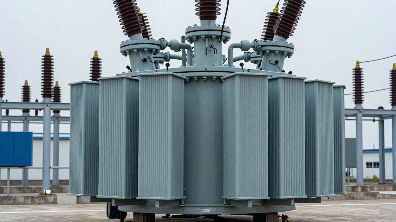
At the 2026 CIGRE Session, HD Hyundai Electric presented a digital-twin-based transformer partial discharge (PD) diagnostic system that models pulse propagation through windings, core, oil and tank from 3D design data, reduces that to a matrix of attenuation, delay and blocking factors, and positions the source from a pre-mapped lookup. Paper A2_11489_2026 reports partial discharge source location from three sensors where the conventional minimum is four, with a 20 % accuracy improvement.
Detection answers one question; location answers another
A single ultra-high frequency (UHF) sensor reporting activity tells you something is discharging somewhere in a tank several metres across: an alarm, but not a work plan. A winding defect, a bushing-end discharge and a loose metallic part all deliver a plausible pulse to the same port. Location is a different measurement: it needs a sharply defined arrival time, several sensors at known coordinates, and a model of the source-to-port path.
Four routes to a position, and where each one breaks down
| Approach | Needs | Breaks down when |
|---|---|---|
| UHF time-of-flight (TOA, TDOA) | Nanosecond synchronisation, known sensor coordinates | Reflections and non-line-of-sight paths shift the leading edge |
| First-peak timing | Wideband capture, a stable trigger | Peak tracks sensor response and input band, not distance |
| Digital-twin pre-mapped table | A validated model of that unit | Model error becomes position error |
| Acoustic triangulation | Wall-mounted sensors, microsecond timing | Attenuated by windings and barriers |
| RF and HFCT amplitude ratio | Several channels, a calibrated reference | Amplitude tracks coupling, so the estimate is coarse |
Time of arrival (TOA) uses absolute times; time difference of arrival (TDOA) uses differences between sensor pairs and cancels the need to know when the pulse started. Dukanac and colleagues, reporting to the Bosnia and Herzegovina CIGRÉ national committee in February 2026, showed with an Ansys HFSS model that changing the input pulse band alters the received waveform and the TOA, TDOA and first-peak values positioning uses. Non-line-of-sight (NLOS) correction with six UHF sensors on a 35 kV transformer reached a minimum calculated error of 10.88 cm, and a particle-swarm method better than 15 cm on a 180 MVA unit, both conference figures not independently verified.
FAQ: What timing accuracy does partial discharge source location need?
One nanosecond or better is the working target: electromagnetic energy covers a good fraction of a metre in that interval, less in oil where propagation is slower, so a nanosecond of timing uncertainty is worth tens of centimetres of position error. The sensor matters as much as the clock: its response shapes the leading edge the acquisition system then times. CIGRE guidance places the best PD detection band at 100 MHz to 1 GHz, with other work using 400–900 MHz.
FAQ: How many UHF sensors does partial discharge source location need?
Three is the practical floor for a three-dimensional time-difference solution, and four the conventional minimum once redundancy matters, so one blocked path cannot collapse the answer. The HD Hyundai Electric work claims three by leaning on a pre-computed model of that transformer rather than geometry alone. More sensors help only if their positions are recorded and their clocks share a time base.
Locate the source, then decide what to open
A located source changes the maintenance decision: it separates a phase-to-tank defect from a loose part in an oil duct, shows where an inspection should begin, and turns waiting into a defined scope. It settles nothing alone, so it is read alongside phase-resolved patterns (see our PRPD and PRPS guide) and dissolved gas analysis. Five PD case studies on oil-filled transformers and shunt reactors at the 2026 CIGRE Session (paper A2_11662_2026) correlate IEC 60270 and UHF measurements with the damage found on inspection.
Designed in line with IEC TS 62478:2016 and its Chinese equivalent GB/T 42287, the TPD-400 online PD monitoring system takes UHF (300–1500 MHz, oil-valve or manhole mounted), RF, acoustic (80–200 kHz) and HFCT (0.3–30 MHz) inputs into one industrial IED, all figures vendor data, with 125 MS/s, 14-bit acquisition, synchronisation under 100 ns, a minimum measurable apparent charge around 5 pC and 600 kV lightning-impulse withstand, from a local cabinet rated −30 to +60 °C on AC 220 V. It can assist partial discharge source location; it does not certify a position. Reporting runs over IEC 61850 (DL/T 860), and the unit pairs with a gas monitor such as the DGA-900 nine-gas analyser.
Talk to us about specifying PD monitoring that can localise, not just detect.
Sources
- CIGRE Session 2026, paper A2_11489_2026 (HD Hyundai Electric): 3D-model propagation matrix, pre-mapped lookup, three-sensor localisation, 20 % accuracy gain.
- CIGRE Session 2026, paper A2_11662_2026 (Türkiye): five PD case studies on oil-filled transformers and shunt reactors, IEC 60270 and UHF against damage found on inspection.
- Dukanac et al., B&H Electrotechnical Journal (CIGRÉ, Bosnia and Herzegovina), February 2026, doi:10.2478/bhee-2026-0019.
- CIGRE brochure: best PD detection band 100 MHz to 1 GHz. Qualitrol whitepaper: time-of-flight localisation as the linchpin for correlating UHF readings with CIGRE thresholds.
- IEC TS 62478:2016 (GB/T 42287 equivalent); IEC 60270; DL/T 1498.1; IEC 61850 (DL/T 860). IEEE C57.127 is acoustic emission only.
- Conference figures supplied for this article, not independently verified: 10.88 cm NLOS correction (35 kV), sub-15 cm particle-swarm (180 MVA), ~1 ns timing target.