
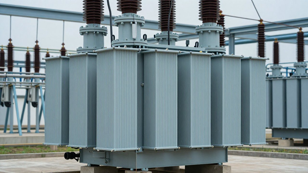
A 2026 CIGRE D1 paper describes online radiometric partial-discharge monitoring across high-voltage air-insulated substation assets; in one 245 kV capacitor-voltage-transformer case it confirmed discharge activity above 300 pC in service, well before a scheduled inspection would have caught it. The same reasoning now reaches inside the transformer tank: online partial discharge monitoring for transformers is becoming a standard line in condition-monitoring RFQs.
What online partial discharge monitoring measures
Partial discharge (PD) is localized electrical breakdown inside insulation that has not yet bridged the gap between conductors. In a transformer it appears as corona, surface discharge, or discharge in gas-filled voids of the paper-oil insulation. Each pulse lasts nanoseconds to microseconds and carries an apparent charge measured in picocoulombs (pC); the pulses repeat in phase with the AC cycle. Plotted phase-resolved, as a PRPD or PRPS pattern, they let an engineer tell a void discharge from surface tracking or corona, and let software classify the pattern automatically. Because PD erodes paper and oil until it becomes tracking, carbonization, and finally a dielectric failure, catching the progression early is the purpose of a continuous monitor.
Four sensing methods, one picture
No single sensor sees every discharge site, so online systems combine sensing methods. The four used on transformers are compared below.
| Method | Sensor location | Typical band | What it catches |
|---|---|---|---|
| UHF | Inside the tank via oil-valve or manhole port | 300–1500 MHz | Internal discharges with low noise pickup; supports time-difference localization |
| HFCT | Clamp around grounding, neutral, or bushing-tap conductors | 0.3–30 MHz | Discharge current pulses on connected metallic paths |
| AE (acoustic) | On the external tank wall | 80–200 kHz | Ultrasonic pressure waves from discharges; useful for localization |
| RF (radiometric) | Near the asset, antenna-based | Broadband | Electromagnetic emissions; also used for switchyard assets |
Band figures are typical manufacturer values (vendor data). The framework for these online, non-conventional methods is IEC TS 62478 and its Chinese equivalent GB/T 42287; laboratory measurement follows IEC 60270. One pitfall: IEEE C57.127 covers acoustic methods only, so it does not justify a UHF or HFCT deployment.
What to look for in a monitoring system
A practical system ties the sensors to a single acquisition unit. When you compare options for online partial discharge monitoring for transformers, start on the acquisition side: synchronous multi-channel sampling in the 100 MS/s class at 12–14 bit, so pulses across sensors can be compared with inter-channel timing skew below 100 ns — the basis for source localization. On the analysis side, look for PRPD/PRPS visualization plus an automatic pattern-recognition engine that classifies discharge type and tracks severity, rather than raw waveforms an engineer must interpret by hand.
Designed in line with those requirements, the TPD-400 online PD monitoring system takes UHF, RF, acoustic, and HFCT inputs into one industrial IED with synchronized acquisition (125 MS/s, 14-bit, vendor data), 2D and 3D phase-resolved plots, and a neural-network pattern-classification engine. Compliance wording matters too: reputable vendors state their equipment is designed in line with IEC TS 62478 and GB/T 42287 for non-conventional online PD measurement, IEC 61850 (DL/T 860) for station communication, and DL/T 1498.1 for online monitoring devices — type-test claims should always be checked against an actual report. A short specification checklist:
- Sensor inputs: UHF (oil-valve/manhole) plus HFCT in one IED, acoustic or RF as options.
- Digitizer: synchronized channels, ~100 MS/s or higher, ≥12-bit, inter-channel sync in tens of nanoseconds.
- Sensitivity: a usable floor in the single-digit pC range (TPD-400 quotes ~5 pC, vendor data) and a stable baseline so trends stay meaningful.
- Diagnostics: PRPD/PRPS plots with pattern recognition and trend-first alarm logic.
- Integration: IEC 61850 (DL/T 860) and Modbus outputs so PD sits beside DGA and load data.
Can PD monitoring be retrofitted without an outage?
Usually yes, and retrofit drives much of the market. A UHF sensor fits through an existing oil drain or sampling valve, and an HFCT clamps around a grounding conductor, so both can be installed on an energized transformer where the site safety procedure allows. For 110 kV and above, Chinese guidance T/CSEE 0421 addresses oil-valve UHF installation and is a useful reference when planning a live retrofit.
Does PD monitoring replace DGA?
No — dissolved gas analysis (DGA) remains the best single indicator of overall fault development, and a dissolved hydrogen sensor is the most economical fleet-wide early warning. PD adds what oil cannot: confirmation that an electrical discharge is active right now, its phase-resolved signature, and a location when multiple sensors are fitted. The practical relationship between the two is laid out in our PD vs DGA comparison; the usual program is DGA or hydrogen across the fleet plus online partial discharge monitoring for transformers on critical units — generator step-ups, interties, and stations with limited redundancy.
Build a transformer condition monitoring program
PAS DGA builds both halves of the picture. The TPD-400 covers the partial-discharge side; the DGA-900 nine-gas monitor and the hydrogen sensor range cover dissolved gas, so one supplier can instrument a transformer for full insulation-condition visibility. Start with the compliance-oriented hydrogen baseline, then add a PD channel where electrical risk is highest.
Talk to us about specifying an online partial discharge monitoring system for your transformers.