
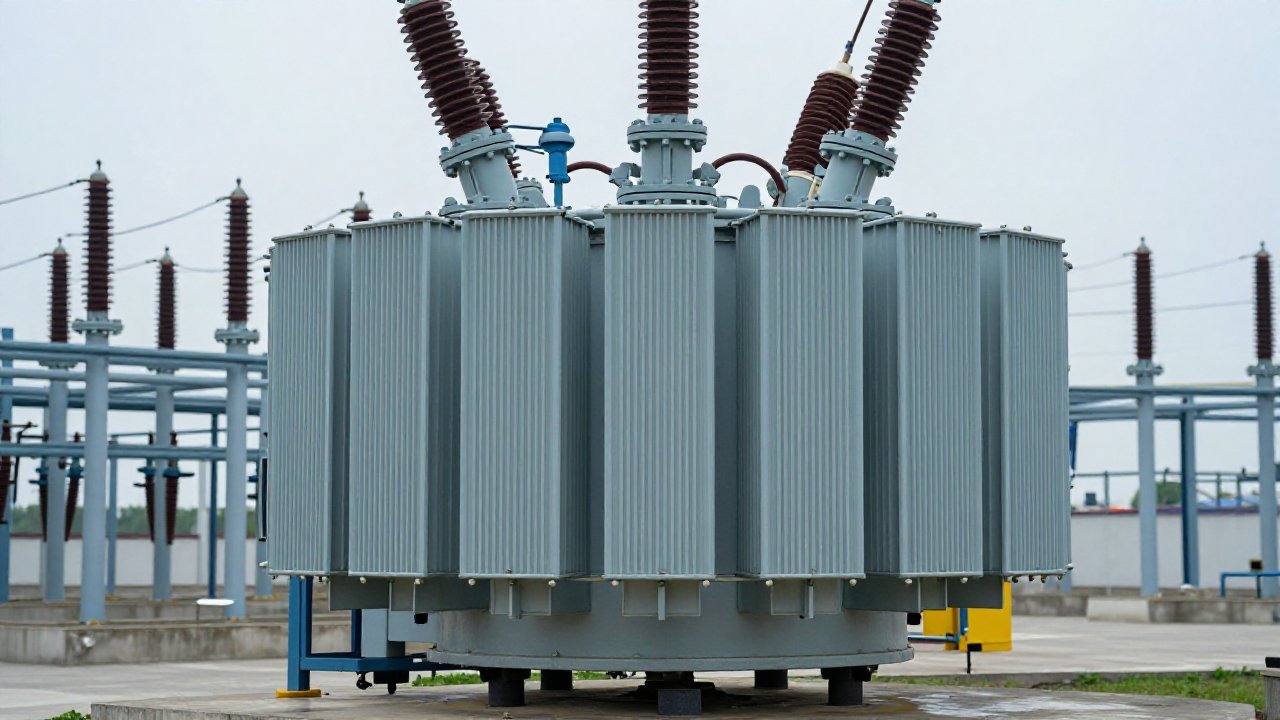
A paper at the 2026 CIGRE Session (D1_10308_2026) reports fiber-optic acoustic sensors on two full-scale bushings, read electrically through the bushing test tap: detection from roughly 80–85 kV inception at around 1 nC. A patent granted on 10 March 2026 (US 12,571,858 B2) adds temperature, pressure, partial discharge current and hydrogen sensing to the bushing’s oil taking port. Bushing partial discharge monitoring is built around a small terminal most people walk past.
The flange tap was always a measurement port
A bushing on a large transformer is a condenser: concentric oil-impregnated paper layers with conductive foils between them, stepping voltage down from the conductor to the flange. The outermost foil comes out at a terminal in the flange — the capacitance tap — earthed in service through its cover. IEC 60270 already treats the bushing tap as a coupling point for conventional PD measurement, and the condenser core is the coupling capacitor. Bushing partial discharge monitoring mostly uses a port that already exists.
CIGRE’s surveys put 14.4 % of transformer failures across all voltage classes on bushings (TB 642) and concentrate bushing failures at 21–30 years in service (TB 755); 47 % carry a serious consequence — fire, explosion or leakage (INMR).
Flange tap, oil valve, tank wall: what each port can see
| Port | Coupling | Reads best | Weak on |
|---|---|---|---|
| Bushing tap, HFCT on the tap lead | 0.3–30 MHz current from the condenser core | Bushing insulation, winding PD near the bushing | Faults deep in the winding |
| UHF sensor, oil valve or manhole | 300–1500 MHz, in-tank | Sources inside the tank | The bushing and its riser |
| Acoustic sensor, tank wall or base | 80–200 kHz mechanical | Bushing base, where CIGRE found highest sensitivity | Long bushing bodies, where sound attenuates |
The riser is the awkward one. A 2026 IEEE CIEEC paper (pp. 1284–1287) calls the bushing riser a compact, high-field component and so a high-incidence area for oil-paper discharge, with external sensors of limited sensitivity there. A UHF port on the tank wall is no substitute for the tap when the discharge is in the bushing.
FAQ: Can bushing partial discharge be monitored on-line?
Through the tap, yes: a high-frequency current transformer on the tap lead is a permanent, low-cost channel, and it is the route the CIGRE work used as its electrical reference. Sensors at the bushing base carry the acoustic route without electrical connection to the primary. Calibration is harder: a pC figure from a tap measurement is not the pC figure of a factory test, so on-line readings are read as trend, not absolute charge.
FAQ: How much partial discharge is acceptable in a bushing?
At the factory, IEC 60137 requires a routine PD test on every bushing, with limits that differ between oil-impregnated and resin-impregnated paper; the standard’s own table is the reference, and resin-impregnated designs commonly list around 10 pC at rated voltage (vendor data). In service the comparison is a change, not a number: a tap reading that climbs over weeks matters more than the level on the day.
Adding a tap adapter is not adding an oil-valve sensor
One caution decides the retrofit: the capacitance tap is earthed in normal service and is not self-grounding. ABB’s bushing manuals state that the test tap must never be open-circuited while the bushing is energised, and warn that an ungrounded tap can destroy it; IEEE/PES Transformers Committee material records tap voltages up to 17 kV if the ground reference is lost. Tap sensors are built for that — OMICRON’s adapters fit Micafil, ABB, F&G and HSP bushings plus IEEE standard taps, with an integrated surge arrester (vendor data) — but the cover comes off only with the unit de-energised and grounded. That is a different job from the oil-valve UHF retrofit, designed to be installed live.
Designed in line with IEC TS 62478:2016 and GB/T 42287, the TPD-400 online PD monitoring system takes UHF, RF, acoustic and HFCT inputs into one industrial IED, with 125 MS/s, 14-bit acquisition, synchronisation under 100 ns, minimum measurable apparent charge around 5 pC and 600 kV lightning-impulse withstand (vendor data). It reads the tank, the riser and the tap lead, and certifies nothing. Reporting runs over IEC 61850 (DL/T 860) and pairs with a DGA-900 nine-gas analyser. Bushing partial discharge monitoring is where the tap channel earns its place.
Talk to us about a monitoring plan that starts from the right port.
Sources
- CIGRE Session 2026, D1_10308_2026 (Optics11; SGB-SMIT Group): fiber-optic AE on two full-scale bushings, electrical PD read via the test tap, ~80–85 kV inception at ~1 nC.
- US 12,571,858 B2, All-in-one sensing apparatus for transformer bushing tap monitoring, State Grid Xinjiang EPRI, granted 10 March 2026.
- Hu et al., Acoustic and UHF Signals for PD in Bushing Riser, IEEE CIEEC 2026, pp. 1284–1287.
- CIGRE TB 642, Transformer Reliability Survey (WG A2.37, 2015); TB 755, Bushing Reliability Survey (WG A2.43, 2019); shares via INMR, Proactive Bushings Management.
- ABB bushing installation and maintenance manuals (GOE, GSB): the test tap must never be open-circuited while energised.
- IEEE/PES Transformers Committee, C57.19.100 material on on-line monitoring through bushing capacitor taps.
- IEC 60137; IEC 60270; IEC TS 62478:2016 (GB/T 42287); DL/T 1498.1; IEC 61850 (DL/T 860).
- OMICRON bushing adapter information; vendor data.