
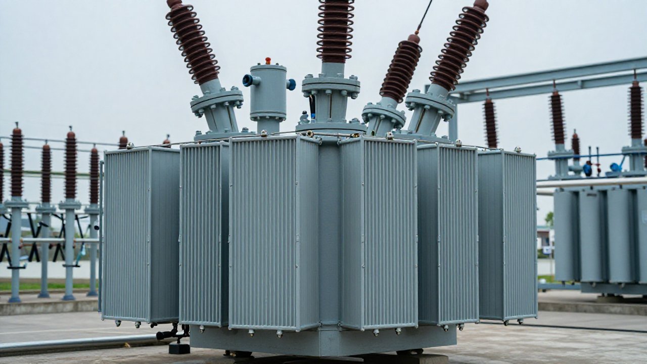
On 5 June 2025 the IEC published Edition 4.0 of IEC 60270, retitled Charge-based measurement of partial discharges. It replaces the 2000 edition and its 2015 amendment, and for higher frequency ranges it hands the reader to IEC TS 62478. The retitling carries the argument: that standard says how to measure a charge, not what reading on a given transformer should wake somebody up. A workable partial discharge alarm threshold is a trend decision before it is a number.
Why one pC value is a poor partial discharge alarm threshold
Apparent charge is a calibrated quantity: it exists only relative to a measurement circuit, a calibrator and a stated test voltage, which is what IEC 60270:2025 defines. Move the coupler along a winding, or from a shielded laboratory into a substation, and the same defect reports a different number.
Online, the gap widens. A UHF coupler reports decibels or millivolts, an HFCT millivolts, an acoustic sensor decibels. None is apparent charge, and no honest factor converts one into a laboratory pC figure.
What changes when the measurement moves online?
Four documents cover the ground.
| Standard | What it gives you | Where it stops |
|---|---|---|
| IEC 60270:2025 | Calibrated apparent charge in pC; measurement and calibration circuits | An in-service alarm level for a transformer |
| IEC TS 62478:2016 (GB/T 42287) | Electromagnetic and acoustic methods; sensor ranges; PD location | A pC number interchangeable with a 60270 reading |
| DL/T 1498.1 | General requirements for on-line monitoring devices | Fault-type diagnosis |
| IEEE C57.127-2018 | Acoustic emission, detection and location | Anything about UHF; AE only |
IEEE C57.113-2023 is the conventional practice for liquid-filled units. None of the four sets a limit for an energised transformer: acceptance levels belong to the apparatus standards, quoted at a defined test voltage in a controlled circuit, and they do not survive the trip to the field.
How do you establish a baseline before you can alarm on trend?
A baseline is not one number. It is the range a unit occupies across the states it normally visits.
- Characterise the site’s noise floor first: drives, switching, radio, welding. A sensitivity check on the coupler belongs here too.
- Record a full load cycle. A week including a weekend is the minimum.
- Plot activity against load and oil temperature. A source that scales with load, one that tracks voltage alone and one that follows temperature are three different problems.
- Write down a reference band, then treat departures from it as the signal.
An alarm configured before any of this describes the substation’s interference, not the transformer.
Should every transformer in a fleet share the same threshold?
No. Two units of identical rating can sit in different noise environments, carry different sensor types and present different coupling paths: equal readings do not mean equal risk, and one partial discharge alarm threshold cannot serve both. Share the procedure instead: what counts as watch, what counts as act, who is called, which inspection follows.
Trend supplies the ranking a level cannot: a slow rise over weeks at modest amplitude deserves more attention than a stable reading sitting above a borrowed figure. The same applies when you read a PRPD pattern, where shape and movement carry more than the peak.
Alarm levels inside a condition-based maintenance program
Condition-based maintenance needs a trigger that produces a work order somebody can staff: three states, not two. Normal; a watch state driven by rate of change; an act state driven by level and trend together. Interference is a fourth condition, but it is not an alarm, and it belongs in the noise-filtering settings.
The return is on the slow axis as much as the fast one. PD answers in microseconds; dissolved gas accumulates over hours and days. Run both and a fleet gets an early electrical warning plus a chemical confirmation of where it is heading. See PD versus DGA and the online versus offline comparison; the programme side is under condition-based transformer maintenance, and the DGA-900 covers the chemical axis.
Trending PD alarms with the TPD-400
The TPD-400 is designed in line with IEC TS 62478:2016 and GB/T 42287 for non-conventional on-line PD measurement, reporting over IEC 61850 (DL/T 860) under DL/T 1498.1. One IED accepts UHF (300 to 1500 MHz at an oil valve or manhole), HFCT (0.3 to 30 MHz), acoustic emission (80 to 200 kHz) and RF inputs, with 125 MS/s at 14-bit, channel synchronisation better than 100 ns, a minimum measurable apparent charge around 5 pC, 600 kV lightning-impulse withstand and a -30 to 60 °C local cabinet (vendor data). Patterns are classified by a pattern-recognition expert system; UHF time-of-flight can assist localisation rather than guarantee it.
Continuous logging produces the reference band those thresholds need. For network rollouts see monitoring for utilities.
Send us the fleet list and we will scope the monitoring points.
Sources
- IEC 60270:2025, Ed. 4.0, “Charge-based measurement of partial discharges”, IEC TC 42, 5 June 2025; replaces Ed. 3.0 (2000) and Amendment 1:2015.
- IEC TS 62478:2016, Ed. 1.0, “Measurement of partial discharges by electromagnetic and acoustic methods”, IEC TC 42; GB/T 42287 (Chinese counterpart).
- IEEE Std C57.127-2018 (acoustic emission only); IEEE Std C57.113-2023 (conventional PD measurement); GB/T 7354-2018; DL/T 1498.1; IEC 61850 (DL/T 860).
- TPD-400 sensor and IED figures: vendor data.