
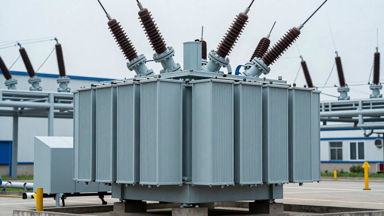
On 12 August 2026 Teledyne FLIR launched the Si2a, its first fixed acoustic camera for continuous partial discharge (PD) monitoring of medium- and high-voltage assets. PD is moving out of the walk-around survey and onto permanent monitoring — and no asset argues for GSU partial discharge monitoring more clearly than the generator step-up transformer. PD is a localised breakdown in insulation that does not yet bridge the electrodes: an electrical event, so it is visible immediately, while dissolved gas analysis (DGA) waits for gas to accumulate in the oil.
Why the Step-Up Transformer Sees the Worst Duty
A generating station concentrates the conditions that age insulation. The step-up transformer interfaces generator and grid, so it runs at high current density and high core flux, is loaded to its rating limit rather than a distribution forecast, and absorbs every load change dispatch makes. Field strength peaks at the winding ends and the tap changer, where cooling is thinnest, and on a baseload unit that duty repeats for months — no quiet period for a routine test to find a slow defect. GSU partial discharge monitoring is installed to close exactly that gap.
Where the Discharge Starts — and Which Channel Sees It
| Location | Why it discharges | Channel that observes it |
|---|---|---|
| Winding ends and lead exits | Peak field strength, sharpest geometry | UHF coupler at the oil valve; HFCT on the earth connection |
| On-load tap changer | Repeated switching duty and its own oil volume | Acoustic sensors on the tank wall |
| Bushings and their taps | External surface contamination and tracking | RF sensing; acoustic, at close range |
| Core and tank joints | Loose metallic contact under stray flux | HFCT on the core earth |
No single channel covers the list: a UHF coupler hears only what propagates to it, an acoustic sensor only what survives the oil and the tank wall, an HFCT only a current with a return path through its core. The four methods and their blind spots are in partial discharge detection methods.
Three Constraints a Generating Station Adds
The first is that the unit cannot be taken out for a routine test on demand, so a survey instrument with limited coverage per visit loses most of its value; permanent sensing reads the defect under real load. The second is electrical noise — the station is full of converters, drives and auxiliary plant — so phase-resolved pattern analysis must separate the defect from the environment, not merely detect energy. The third is that the fastest escalation path on site is a trip, so an alarm that cannot be trusted is worse than no alarm. Together they argue for a device that compares channels against each other and against a unit’s own history, the same discipline used on the gas side (PD versus DGA).
Does GSU Partial Discharge Monitoring Replace DGA on the Main Transformer?
No. The two observe different things. PD shows live activity and can be located; DGA shows accumulated chemical damage and names the fault type once enough gas has formed. On a step-up transformer the useful arrangement is the standard one: PD as the fast channel, gas as the confirming and classifying channel, sharing one set of alarm thresholds. Replacement decisions hinging on the gas trend alone are covered in GSU transformer replacement; PD monitoring in power generation sets out the equipment classes involved, and utility-scale PD monitoring covers the transmission-side equivalent.
What Does the Detector Actually Report in a Generating Station?
The non-conventional methods report in decibels or millivolts, not picocoulombs. IEC TS 62478 covers measurement by electromagnetic and acoustic methods, adopted identically as GB/T 42287, with DL/T 1498.1 governing online monitoring devices as a class; the conventional charge-based method is IEC 60270, and IEEE Std C57.127 addresses acoustic detection only, so it cannot justify a UHF or HFCT channel. None of these documents type-tests an instrument — “designed to IEC TS 62478” describes a method, not a certificate. In practice each channel is anchored to the unit’s own baseline.
PAS DGA for PD Monitoring on Generator Step-Up Units
The TPD-400 is a permanent monitoring IED with four sensing inputs — UHF couplers (300–1500 MHz, oil valve or manhole), HFCT (0.3–30 MHz, earth connection), acoustic sensors (80–200 kHz, tank wall) and radio-frequency sensing. It samples at 125 MS/s, synchronises channels to better than 100 ns, resolves apparent charge to roughly 5 pC, withstands 600 kV lightning impulse and runs from an AC 220 V cabinet over −30 to 60 °C (vendor data). It is designed in line with IEC TS 62478 / GB/T 42287 and DL/T 1498.1, over IEC 61850 (DL/T 860) and Modbus. Where the fault type has to be named, DGA-900 adds nine-gas and moisture analysis to the same scheme. Send us the unit rating and the tank ports for a channel plan — contact us.
Sources
- Teledyne FLIR, Si2a fixed acoustic imaging camera for continuous partial discharge monitoring, announced 12 August 2026: classification up to 200 m, IP66 enclosure.
- IEC TS 62478:2016, measurement of partial discharges by electromagnetic and acoustic methods (= GB/T 42287), no new edition as at September 2026; IEC 60270:2025 (Ed. 4.0), charge-based measurement; IEEE Std C57.127-2018 (acoustic only); DL/T 1498.1 (online monitoring devices).
- Power plant electrical equipment online monitoring review, May 2026: generator stator PD monitoring (3PARD) plus main and step-up transformer PD, DGA and bushing monitoring.
- TPD-400 technical data, pasdga.com/products/tpd-400/, accessed 1 October 2026 (vendor data).