
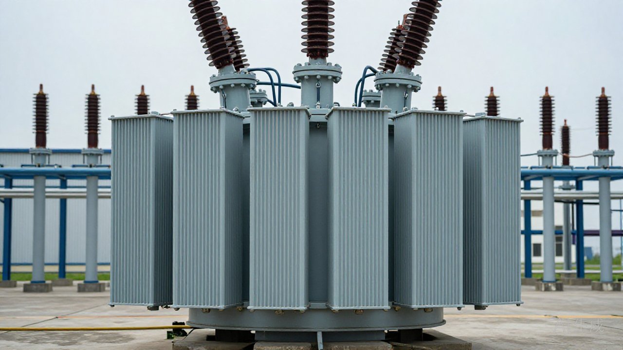
In January 2026 IEEE Transactions on Dielectrics and Electrical Insulation published a comparison of UHF partial discharge localisation on two 220 kV transformers — one fitted with six built-in UHF sensors, the other with eighteen. More sensors did not keep improving the answer. Five or six, distributed around the tank, gave the best accuracy, and a timing error of about one nanosecond still moved a computed source by tens of centimetres. That study answers the question behind every multi-channel PD measurement specification: how many channels does a transformer need?
What a channel actually buys
A discharge radiates energy that must reach a coupler before it can be recorded. A channel is one such path: one sensor, one cable, one acquisition input. Adding a channel does not make the instrument more sensitive; it adds a second place from which the same event can be seen. Two views settle what one cannot: a pulse seen at the same instant on an oil-valve UHF antenna and a tank-wall acoustic sensor is inside the tank; a pulse reaching only the antenna, at the same point in every cycle, is more likely conducted noise.
That is why UHF, HFCT and acoustic sensing are complementary rather than ranked. Each couples to a different physical quantity, so each is blind to something the others see.
The 2026 evidence on sensor count
The IEEE study is not alone. A Chinese patent published in March 2026 (CN120801955B) specifies at least four non-coplanar, non-collinear UHF sensors for three-dimensional positioning, synchronised by BeiDou or GPS pulse-per-second signals. A CIGRE 2026 session paper from HD Hyundai Electric claimed a digital-twin model that locates a source with three sensors instead of four, with a 20 per cent accuracy gain; conference figures are vendor-reported, not independently verified.
Read together, the sources agree on a floor and a ceiling: three sensors locate a source only with a validated model, four is the conventional minimum for time-difference localisation, and beyond five or six the marginal value falls unless the extra sensors are placed well and share a clock.
| Channels | What it supports | Main caveat |
|---|---|---|
| 1 | Trend and alarm only, no location | Depends on defect distance from that coupler |
| 3 | Localisation with a validated propagation model | Model error passes into the answer |
| 4 | Conventional 3D time-difference minimum | Non-coplanar placement and nanosecond timing required |
| 5–6 | Best accuracy in the 2026 IEEE validation | Placement must wrap the tank, not cluster on one side |
| More than 6 | Coverage on very large or multi-compartment units | Marginal unless coordinates and clock are known |
Where the channels go
Count is the easier half; placement decides whether it means anything. In the 2026 study, sensors clustered on one side or in adjacent areas were less robust than sensors distributed around the transformer — a defect radiates toward the nearest coupler, and three sensors on one face triangulate badly.
For a large oil-immersed unit the working map has four positions: an oil-valve or manhole UHF coupler for in-oil pulses, a bushing tap or earthed flange for HFCT or RF current, an acoustic sensor on the tank wall, and a dedicated channel for the on-load tap-changer compartment, which is electrically and acoustically its own space. Reading them together is covered in three-phase PRPD analysis.
Synchronisation is the real ceiling
Every number above assumes the channels share a clock. TPD-400 specifies multi-channel synchronisation better than 100 ns, 125 MS/s sampling at 14-bit resolution and a minimum measurable apparent charge of about 5 pC — vendor data. That is adequate for comparing channels and trend work; nanosecond localisation is stricter, and it is where GPS- or BeiDou-referenced systems earn their cost.
Without a common time base, channels still detect but cannot be compared, leaving several independent alarms instead of one diagnosis.
How many channels does a transformer need?
For a single large power transformer, four to six channels cover the common specification: one or two UHF couplers in oil, one HFCT or RF path, one acoustic channel and, where fitted, a tap-changer channel. Small or non-critical units can run fewer: the requirement is an alarm and a trend, not a location.
Can channels be added to a running transformer?
Usually yes — the argument for multi-channel PD measurement as a retrofit. Oil-valve UHF couplers and tank-wall acoustic sensors can be fitted without an outage on most designs, and HFCT clamps close around existing earth connections. The constraint is rarely the sensor; it is whether the unit has spare inputs and whether the new channel can join the same time base.
Multi-channel PD measurement is not a specification line to maximise. It is a way of deciding what a pulse is by seeing it from more than one place, and the 2026 literature is unusually clear that five or six well-placed channels do more than a larger array. For the wider argument about which method answers which question, see PD monitoring versus dissolved gas analysis; where gas and discharge data are read together, the multi-gas DGM-900 supplies the chemical side. Utility fleets weighing retrofit order can start from the power-utilities application notes, and installation documents sit in the manuals library. To size a system against a specific transformer, send the nameplate and the tank drawings.
Sources: IEEE Transactions on Dielectrics and Electrical Insulation, pulse-injection UHF validation study, January 2026; CN120801955B (2026-03-31); CIGRE 2026 Session, digital-twin PD diagnostics (conference paper, vendor-reported); IEC TS 62478.