
TPD-400 — Transformer Partial Discharge (PD) On-line Monitoring System
Multi-sensor partial-discharge monitoring for 110 kV+ oil-immersed power transformers — UHF (300–1500 MHz) · RF · Acoustic AE · HF (HFCT) — installed live, without de-energizing the transformer.
Product Overview
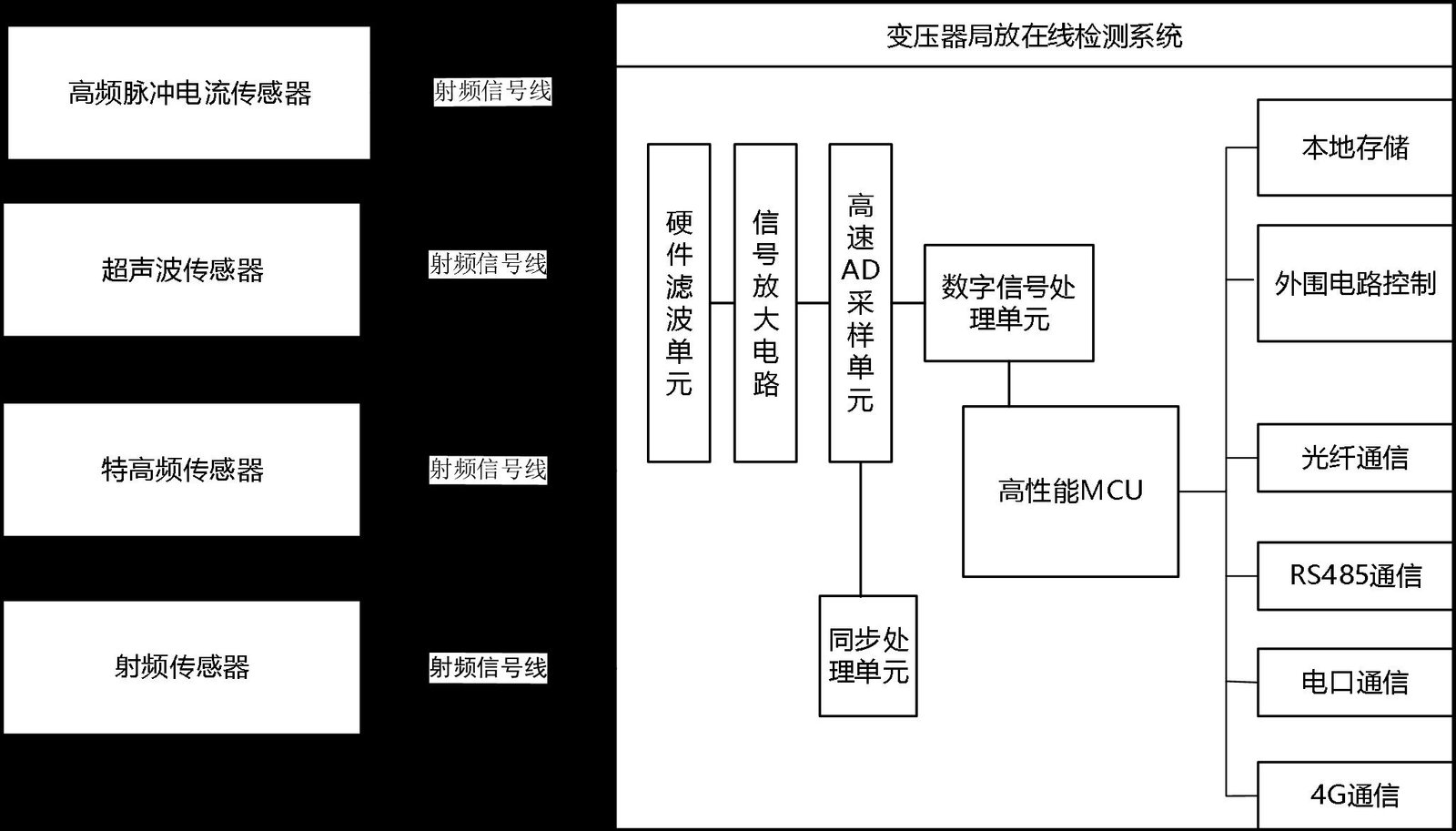
The TPD-400 is a multi-sensor, on-line partial-discharge (PD) monitoring system for the insulation-condition monitoring of 110 kV and above oil-immersed power transformers. It continuously acquires PD activity using four complementary sensing techniques: UHF (300–1500 MHz) and RF broadband electromagnetic sensing, AE acoustic-emission (ultrasonic) sensing at 80–200 kHz, and HF high-frequency pulse-current sensing via a clamp-on high-frequency current transformer (0.3–30 MHz).
Because an internal discharge radiates both GHz-class electromagnetic energy and acoustic pressure waves, and couples pulse currents into the transformer earth conductors, fusing the four methods gives the TPD-400 high detection sensitivity, strong on-site anti-interference capability, and the ability to classify defect type and trend severity — in live substation electromagnetic environments where conventional IEC 60270 pulse-current measurement is impractical. Minimum detectable discharge is 5 pC, and the acquisition unit withstands a 600 kV flashover impulse without damage or data loss.
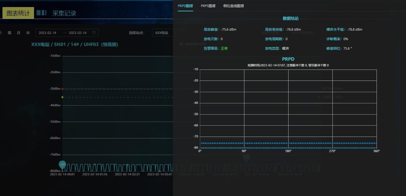
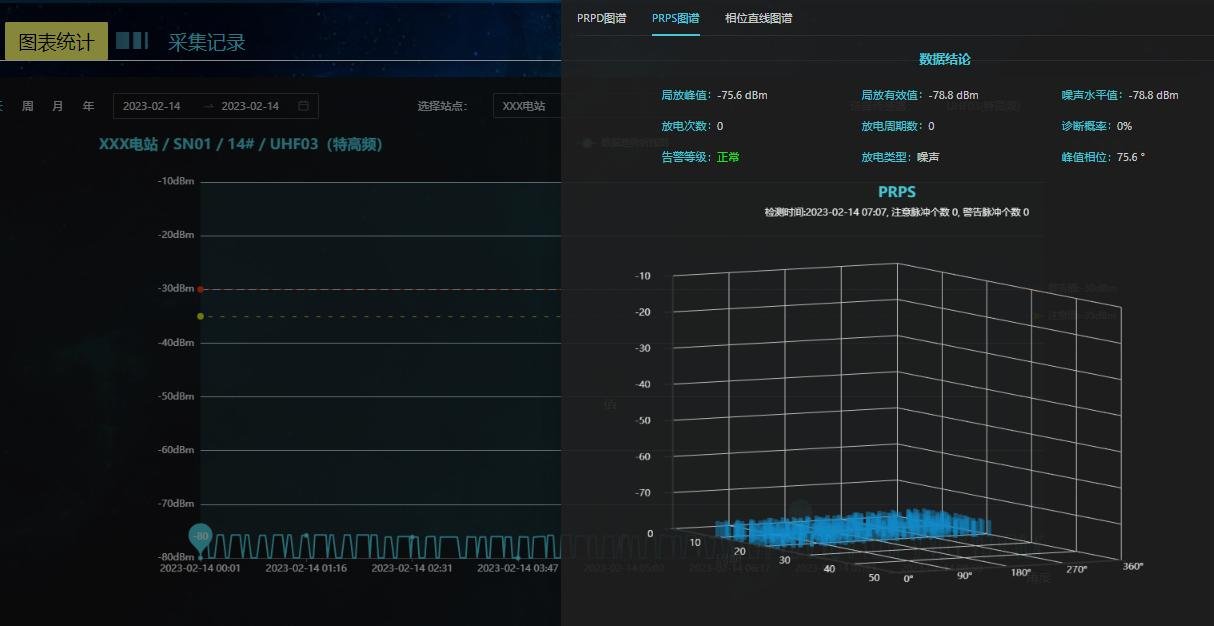
The system is designed for energized (live) installation: sensors are fitted to the transformer tank, drain valve / hand-hole, core-clamp earth and radiator areas without changing the transformer’s internal structure, sealing or insulation. A rack-mount PD acquisition unit (IED) digitises and phase-synchronises the sensor signals; a host data server and browser-based analysis software present PD trend charts and phase-resolved maps (PRPD / PRPS / phase-linear), compare patterns against an expert discharge library, and issue alarms.
PD + DGA — why the two belong together
PD responds in real time to discharge-type faults; DGA confirms and classifies gas-derived faults after gases dissolve and equilibrate. Used together they cut both false alarms and missed events — the industry-standard combination for transformer condition monitoring. See PD vs DGA monitoring compared.
Sensing Principles
A partial discharge inside an oil-immersed transformer produces three physically independent signatures, and the TPD-400 measures all of them:
UHF / RF electromagnetic
The first current pulse is ~1 ns wide, so its spectrum extends beyond 1 GHz. Corona-dominated site noise concentrates below ~300 MHz — sensing at 300–1500 MHz avoids the dominant interference and gives high sensitivity to internal PD.
Acoustic emission (AE)
PD radiates pressure waves in oil that reach the tank wall. Contact AE sensors (80–200 kHz) mounted on the tank wall detect them and support defect location.
High-frequency current (HF)
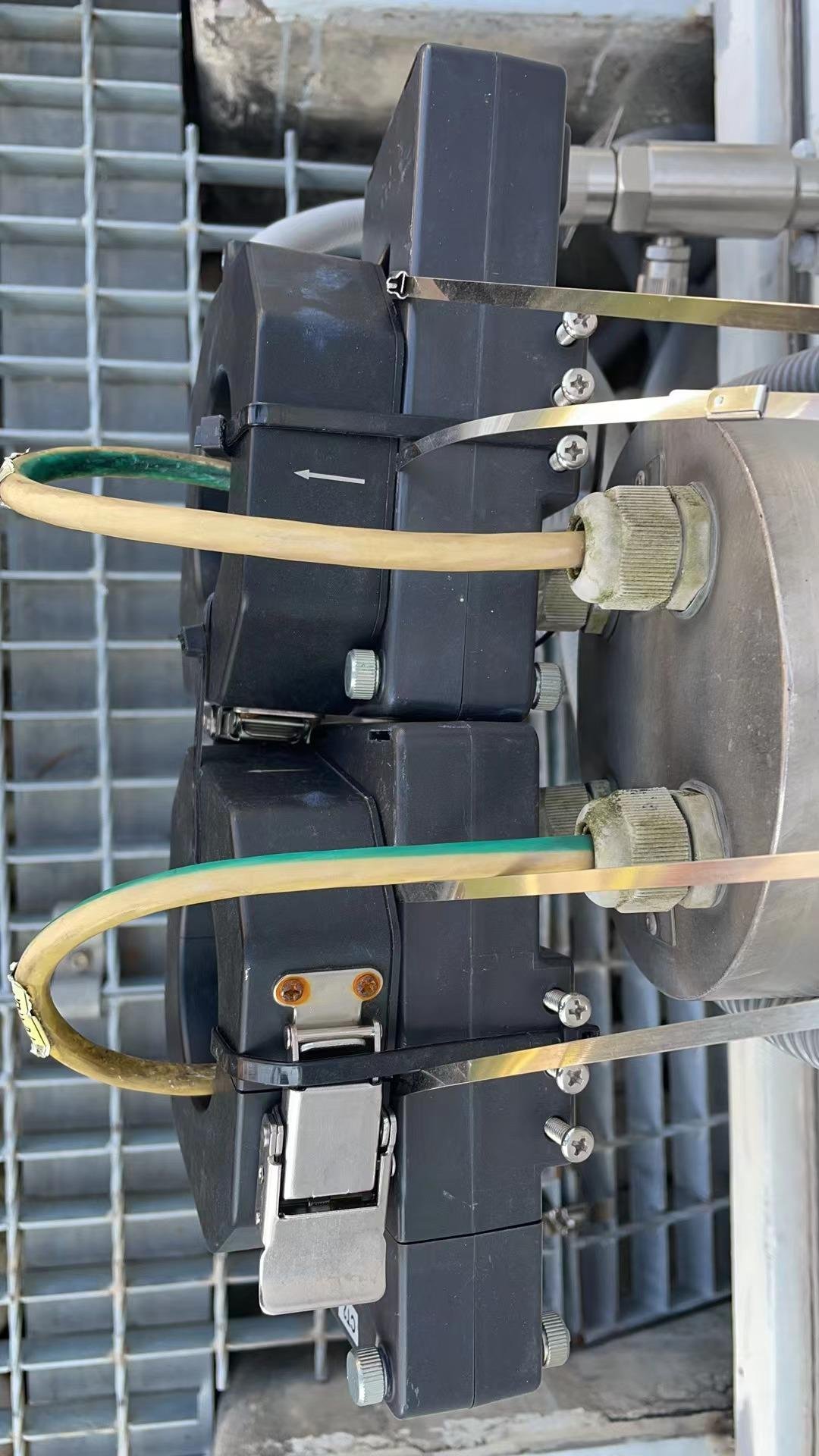
PD pulse currents couple into the core-clamp earth, tank earth and cable screens. A clamp-on HFCT (0.3–30 MHz) detects them without interrupting the circuit.
Measuring all three signatures reduces blind spots and lets the expert system separate true PD from external interference by correlation. The acquisition unit samples at 125 MS/s, 14-bit, phase-synchronises to the power-frequency voltage (external-voltage or internal sync), and time-stamps every group of PD data — typically over ~50 power-frequency cycles per acquisition window for statistically stable maps.
System Architecture & Components
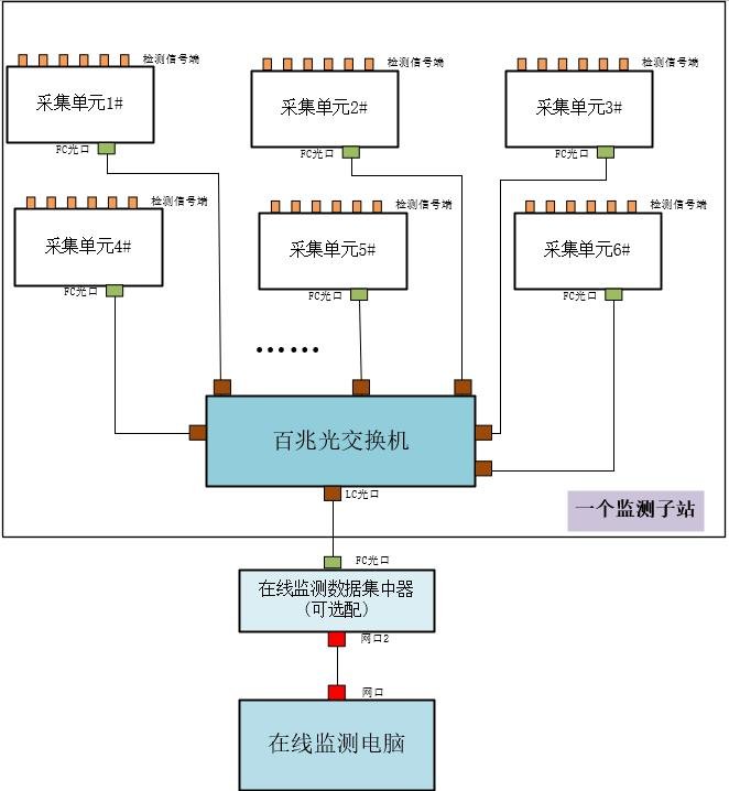
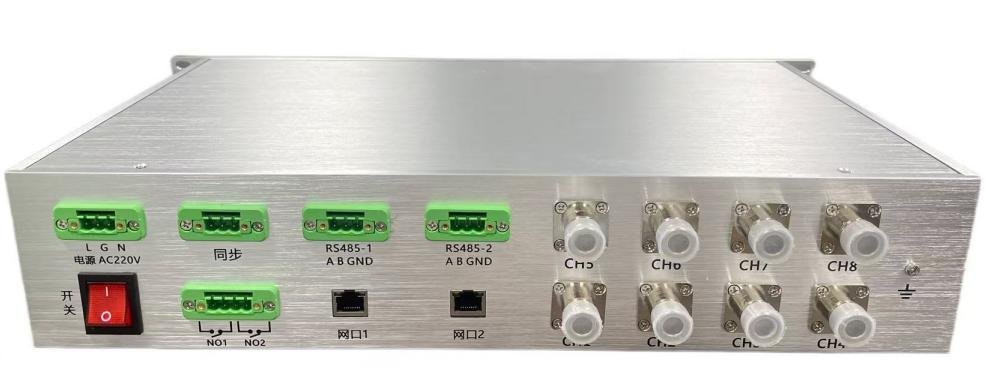
Each PD acquisition unit (IED) conditions the sensor signals, digitises them, stores data locally at the edge, and transmits on demand to the data server — systematic, complete capture with no missed PD events and no communication congestion.
| Sensor | Detection Band | Key Parameters | Typical Mounting |
|---|---|---|---|
| UHF (built-in / external) | 300 – 1500 MHz | Avg. effective height ≥10 mm; 50 Ω coax; resolution 0.1 dBm; dynamic ≥60 dB; range −80 … −10 dBm | Internal (oil-valve / hand-hole / tank fitment) or external |
| RF (broadband) | 300 – 1500 MHz | 0.1 dBm; ≥60 dB dynamic; −80 … −10 dBm; 50 Ω coax | External antenna / sensor head |
| AE (contact ultrasonic) | 80 – 200 kHz (centre 150 kHz) | Piezo element, 67 dB; gain 20–60 dB; dynamic >40 dB; linearity <±20%; 50 Ω coax | Magnetic mount on tank wall — 2 per side on the three non-HV-bushing sides |
| HF (high-frequency current) | 0.3 – 30 MHz | Transfer impedance ≥10 mV/mA; 50 Ω input; gain 0–30 dB; filter 3 M / 300 k / 100 k–30 MHz | Clamp-on (open-core) around core-clamp earth, tank earth, cable screen/armour |
Interconnection to the IED is 50 Ω coaxial: UHF/RF N–N, AE N–M5, HF N–BNC. IED ↔ server by fibre / wired network / RS-485 / 4G per site distance.
Technical Specifications
| Application | On-line PD monitoring of 110 kV+ oil-immersed power transformers (UHF, RF, HF & AE) without outage |
| Minimum detectable discharge | 5 pC |
| Impulse withstand | 600 kV flashover — unit not damaged, data not lost |
| Operating temperature / RH | −30 °C … +60 °C / ≤95% |
| Power supply | External AC 220 V |
| Sampling / resolution | 125 MS/s / 14 bit |
| Channels / synchronisation | Multi-channel synchronous (16-channel platform, configured per project); external-voltage or internal sync; common-trigger skew <100 ns |
| Acquisition window | Statistical processing over ~50 power-frequency cycles |
| Data handling | Local storage + edge processing; peak/RMS + time-stamp per cycle; on-demand upload |
| Communications | Optical fibre / wired network / RS-485 / 4G; IEC 61850 (DL/T 860) integration (†, option) |
| Software | Browser-based; trend / PRPD / PRPS / phase-linear (Q-φ / N-φ) / ellipse; thresholds & ranges per sensor; expert & neural-network diagnostics |
| Mounting | Sensors: tank / valve / hand-hole / clamp; IED: rack-mount in local (marshalling) cabinet |
Compliance orientation: engineered per IEC TS 62478 / GB/T 42287 non-conventional PD measurement, IEC 60270 (incl. Ed.4:2025), IEEE C57.127 / C57.113, DL/T 1498.1 and DL/T 1694.1 design context. Formal third-party type/EMC test reports, where evidenced, are supplied with the controlled datasheet (†).
Software & Displays
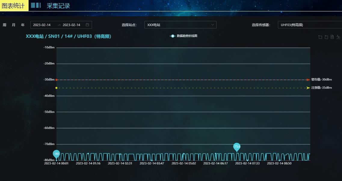
The browser-based analysis software needs no client installation: site overview, per-sensor status, long-term trend analysis, detailed spectrum analysis (PRPD / PRPS / phase-linear / ellipse), alarm handling, threshold & range configuration, and historical data query — with an expert discharge library and neural-network fault library for defect-type classification and risk evaluation.
Installation
Live-installable: access does not alter the transformer’s internal structure, sealing or insulation. Three retrofit schemes are supported:
Oil-valve / hand-hole UHF
Fit the adapter flange to the sampling-valve mouth, push the coupler through the open valve to the root, secure and fit the weatherproof detector housing. Internal UHF gives the strongest signal.
AE tank-wall sensors
Contact AE sensors mount magnetically on the tank wall — two per side on the three non-HV-bushing sides — with acoustic coupling.
HFCT clamp-on
Clamp the open-core HF sensor around the core-clamp earth, tank earth cable or cable screen/armour — no circuit interruption.
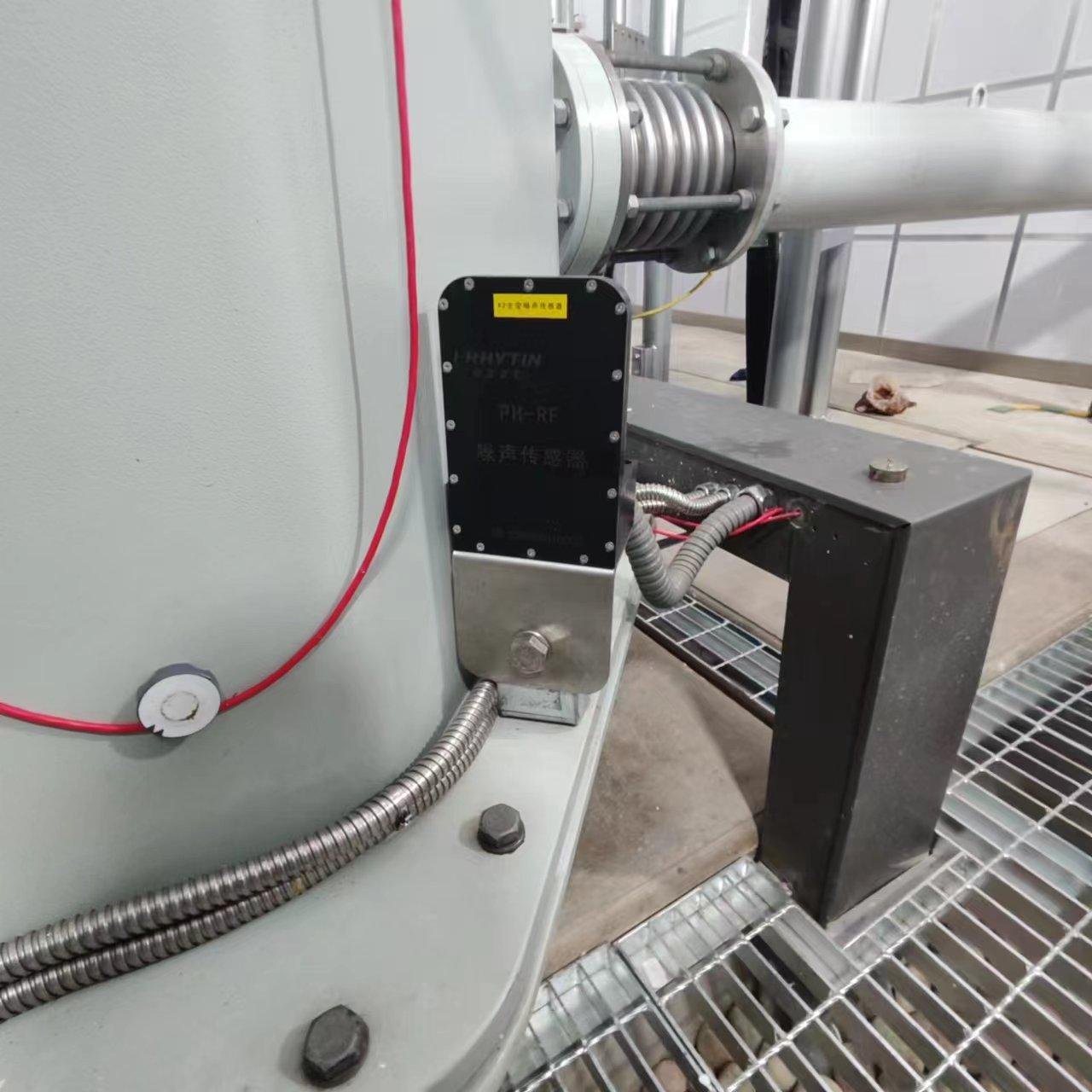
Cabling: sensor ↔ IED by 50 Ω coaxial; IED ↔ server by screened twisted pair (≤100 m), multimode fibre (100 m–2 km) or single-mode fibre (>2 km); AC 220 V to the cabinet/IED.
Configurations & Ordering
Match the TPD-400 to the asset criticality and budget. Sensor quantities, filter bands and communications are configured per project.
TPD-400-U
- IED + internal (oil-valve / hand-hole) or external UHF/RF sensors
- Cabling kit included
- For highest-sensitivity internal PD detection
TPD-400-C
- UHF + HF (+ AE option) package
- Broadest coverage & best noise rejection
- Fully assembled, factory-tested
TPD-400-H / -A
- TPD-400-H: IED + clamp-on HFCT sensors
- TPD-400-A: IED + contact AE sensors + magnetic mounts
- Cost-effective single-method retrofits
TPD-400-OEM
Sensing core and acquisition platform for private-label and integrated transformer-monitoring solutions — including pairing with PAS DGA gas monitors. OEM & partnership inquiry →
Applications
Power Utilities
Transmission and distribution transformer fleets — 110 kV upward, including critical >220 kV units.
Industrial & Commercial
Steel, petrochemical, cement, data-center and traction main transformers.
Renewables & Remote Sites
Wind, solar, hydro and offshore substations where access and outages are costly.
DGA + PD Complements
Add PD to an existing DGA-900 / DGA-700 program for combined condition monitoring.
Explore Transformer Monitoring Products & Technology
PAS DGA — Transformer Condition Monitoring, a brand of VA Technology Co., Ltd. Product and system images on this page are representative illustrations. Detailed installation drawings, controlled datasheets and certified test reports available on request. Email inquiry@pasdga.com. Specifications subject to change without notice.